


Table of Contents
1.1kV aluminium armoured cable is manufactured in single core, twin core, three core and four core configurations, and each option fits a distinct set of applications. Choosing the wrong core configuration can mean an oversized neutral conductor sitting unused, an undersized neutral overheating under load, or unnecessary installation complexity from using multiple single core cables where a multicore cable would have worked just as well. This comparison sets out where each configuration fits and why.
Single Core Aluminium Armoured Cable Explained
Single core aluminium armoured cable carries one conductor per cable, and multiple single cores are run together, typically in trefoil formation, to complete a three phase circuit. This configuration is used where current levels are very high, since a single very large multicore cable becomes difficult to handle and terminate, while several single core cables of a more manageable size can be installed and terminated more easily.
When Should You Use Single Core Aluminium Armoured Cables
Single core cable is the preferred choice in a specific set of high current applications where multicore construction becomes impractical or where the connection geometry itself calls for individual conductors.
Application | Why Single Core Aluminium Cable Fits |
Transformers | Very high secondary current at transformer terminals often exceeds practical multicore cable size, and single core cables in trefoil or flat formation connect transformer bushings to the LT panel efficiently |
MCC Panels | Incoming feeders to motor control centres from transformers or main panels frequently carry high current, and single core cables simplify termination at large bus bar connections |
Bus Duct Connections | Where a cable transitions into a bus duct or rising main, single core cables terminate cleanly onto individual bus bar phases without the bulk of a multicore gland |
Beyond these three common cases, single core cable is generally reserved for circuits above a certain current threshold, often in the range of 400 Amps and above, where the equivalent multicore cable would be too large in diameter to handle, bend and terminate practically on site.
Twin Core Aluminium Armoured Cable and Its Typical Use
Twin core, or two core, aluminium armoured cable carries a phase and a neutral, or two phases for certain control applications, and is used mainly for single phase power circuits. Street lighting feeders, single phase distribution boards and smaller single phase equipment connections are common applications, since a full three or four core cable would be unnecessary where only two conductors are required.
Three Core Aluminium Armoured Cable for Balanced Loads
Three core aluminium armoured cable carries the three phase conductors without a separate neutral, and is used for balanced three phase loads that do not require a neutral connection, such as motor feeders where the motor itself has no neutral requirement. This configuration saves on conductor material compared with a four core cable when the circuit genuinely has no neutral current to carry.
Four Core Aluminium Armoured Cable for Circuits Needing a Full Neutral
Four core aluminium armoured cable includes a full size fourth conductor for the neutral, matching the phase conductor size, and is specified where a circuit is expected to carry significant neutral current, commonly in circuits feeding lighting loads, IT equipment or other single phase loads distributed across the three phases in an unbalanced pattern. The full size neutral in a four core cable safely carries higher neutral current than the reduced size neutral found in a 3.5 core cable.
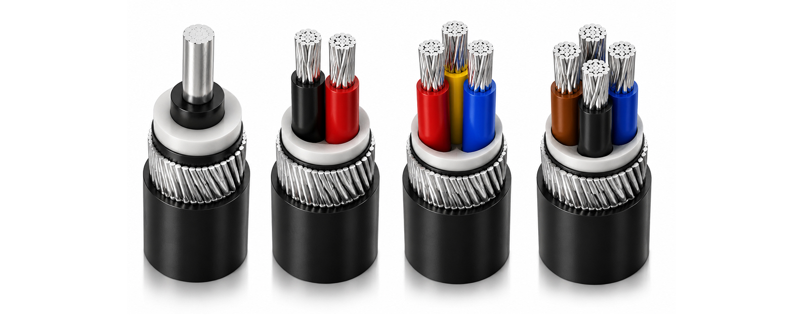
Comparison Table for Quick Core Configuration Reference
Core Configuration | Conductors Carried | Typical Application |
Single core | One conductor per cable, multiple run together | High current transformer, MCC and bus duct connections |
Twin core | Phase and neutral, or two phases | Single phase power and lighting feeders |
Three core | Three phase conductors, no neutral | Balanced three phase motor and power circuits |
Four core | Three phase conductors plus full size neutral | Circuits with significant expected neutral current |
Point of Interest
Trefoil formation for single core cables is specified in many high current installations because it reduces the magnetic field imbalance and associated heating effects that can occur when single core cables are laid flat and widely spaced, particularly on long parallel runs carrying heavy current.
Practical Selection Guidance by Circuit Type
- For transformer secondary connections above typical multicore practical limits, specify single core aluminium armoured cable in trefoil formation.
- For single phase distribution boards and street lighting, specify twin core aluminium armoured cable sized to the connected load.
- For balanced three phase motor feeders without a neutral requirement, specify three core aluminium armoured cable.
- For distribution circuits feeding significant single phase or non linear loads, specify four core aluminium armoured cable with a full size neutral.
- Where neutral current is expected but modest, a 3.5 core cable with a reduced size neutral offers a middle ground between three core and four core options.
Termination Considerations Across Core Configurations
Termination complexity generally increases with the number of separate conductors and with individual conductor size. Single core cable terminations at transformers and bus ducts require careful attention to phase spacing and support, since these connections often sit close to other live equipment. Multicore terminations at panels are comparatively straightforward, with the main consideration being correct lug sizing for each conductor within the cable, including the neutral conductor where its cross section differs from the phase conductors.
Testimonials
“Capital Cables supplied high-quality Aluminium Armoured Cables for our industrial power project. The cable performance, durability, and timely delivery helped us complete the installation without delays.”
– Jay Patel
Sourcing the Right Core Configuration for Your Project
Capital Cables (India) Pvt. Ltd. supplies 1.1kV aluminium armoured cable across single core, twin core, three core, 3.5 core and four core configurations, sourced from leading Indian brands as an authorised dealer and distributor. Matching the correct core configuration to each circuit, from transformer connections through to lighting distribution, avoids both unnecessary material cost and undersized neutral conductors on projects with unbalanced or non linear loads.
Cable Diameter and Bending Radius Across Core Configurations
Cable diameter increases with both conductor size and core count, and this has a direct effect on installation practicality. A four core cable of a given conductor size will have a noticeably larger overall diameter than a three core cable of the same conductor size, which affects minimum bending radius, gland size, tray fill calculations and the physical effort required to pull the cable through ducts or lay it into trenches. Consultants planning cable routes with tight bends or congested duct banks should factor overall cable diameter into the routing design, not just the electrical rating of the conductor.
Consideration | Effect of Higher Core Count |
Overall cable diameter | Increases with each additional conductor |
Minimum bending radius | Generally increases, requiring more space at direction changes |
Gland and termination size | Larger glands needed to accommodate bigger cable diameter |
Tray fill percentage | Higher core count cables consume more tray cross section area |
Selecting Between Multiple Single Core Cables and One Multicore Cable
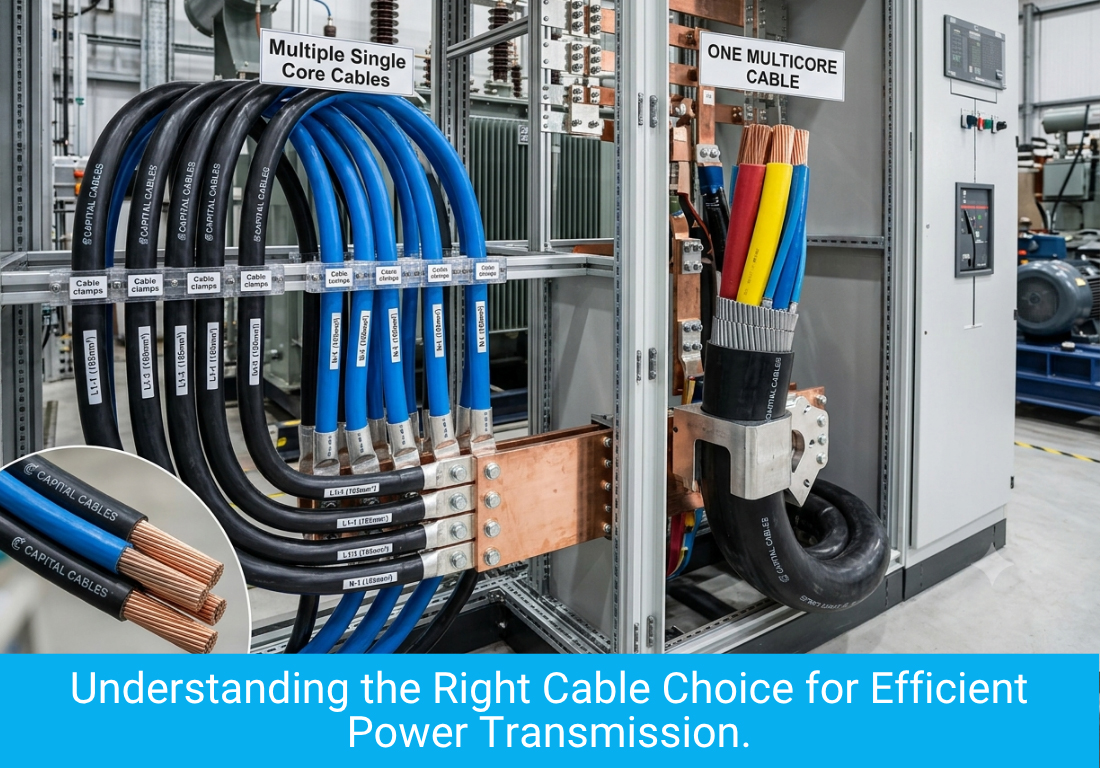
At very high current levels, engineers face a further choice beyond core count, whether to install several single core cables per phase in parallel or to use a small number of very large multicore cables. Running cables in parallel spreads current across multiple smaller conductors, which can simplify handling and termination compared with one extremely large conductor, provided the parallel cables are installed with matched lengths and consistent routing to maintain balanced current sharing between them. This decision typically applies at the highest current levels found in transformer connections and main incoming feeders to large panels.
Cost Comparison Across Core Configurations for the Same Load
Comparing total conductor material across configurations for a circuit that genuinely needs no neutral shows that a three core cable is the most economical choice, since a four core cable for the same phase current adds the material cost of a full size fourth conductor that would sit largely unused. Where neutral current is a genuine design requirement, however, the additional cost of the four core cable is a necessary investment in circuit reliability, since an undersized or absent neutral on a circuit with real neutral current can lead to overheating and premature cable failure.
Reviewing Core Configuration at the Panel Design Stage
Core configuration decisions are best made during panel and single line diagram design, before gland plates are cut and cable schedules are finalised, since changing from a three core to a four core cable late in a project can require rework of gland plate openings and busbar connection points. Design engineers reviewing a single line diagram should confirm the neutral requirement of each feeder against the actual load type connected, rather than applying a single default core configuration across an entire panel schedule.
Summary Guidance for Core Configuration Selection
Choosing between single core, twin core, three core and four core aluminium armoured cable ultimately comes down to matching the cable construction to the actual electrical requirement of each specific circuit, rather than applying a single configuration by default across a whole project. Reviewing current level, neutral current expectation and installation geometry for each feeder individually produces a design that is both technically correct and cost efficient across the full scope of a project.
Buyers and consultants working across large projects with dozens of individual feeders often find it useful to build a simple reference table matching load type to recommended core configuration early in the design process, reducing the risk of inconsistent choices being made by different team members reviewing different sections of the same project over time.
Table of Contents