

Table of Contents
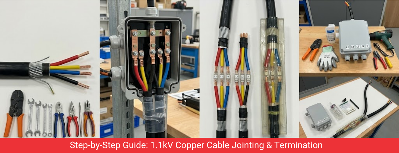
Termination and jointing are the two points in any 1.1kV copper cable installation where failures most often occur, because these are the locations where insulation is cut, conductors are exposed and mechanical connections are made. A cable manufactured to the highest quality standard can still fail in service if it is terminated or jointed incorrectly. This guide sets out the accepted methods, tools and inspection steps for copper cable termination and jointing at 1.1kV, drawn from standard industry practice and Indian Standard guidance.
Difference Between Cable Termination and Cable Jointing
Termination is the process of connecting the end of a cable to a piece of equipment, such as a panel, transformer, motor or switchgear terminal. Jointing, also called splicing, connects two lengths of cable together, typically when a cable run exceeds the standard drum length or when a damaged section of cable must be replaced. Both processes require the armour to be earthed, the insulation to be restored to its original electrical strength and the conductor joint to carry full rated current without excessive resistance.
On a typical project, termination points far outnumber joint points, since every panel, motor and piece of switchgear needs a termination while joints are used only where the route length or a repair genuinely requires one. Planning drum lengths carefully at the procurement stage reduces the number of joints needed on a project, which in turn reduces the number of points on the network where a workmanship error could later cause a fault.
Tools and Materials Required for Copper Cable Termination
Item | Purpose |
Cable stripping tool | Removes outer sheath and armour without damaging the conductor insulation |
Armour clamp or gland | Secures and earths the steel wire or steel strip armour at the entry point |
Copper lugs or crimping terminals | Provide a solid mechanical and electrical connection to the busbar or terminal |
Hydraulic or mechanical crimping tool | Applies correct pressure to form a low resistance crimp on the lug |
Heat shrink or cold shrink termination kit | Restores insulation and provides stress control at the cable end |
Megger or insulation tester | Confirms insulation resistance before energising the circuit |
Torque wrench | Ensures terminal bolts are tightened to the specified value, avoiding loose or overtight connections |
Step by Step Method for 1.1kV Copper Cable Termination
- Cut the cable to the required length and remove the outer PVC or FRLS sheath over the length specified in the termination kit instructions.
- Expose the armour and fit the armour clamp or gland body, ensuring the armour wires are evenly gripped and the gland is earthed to the equipment body.
- Remove the inner sheath and separate the individual cores without nicking the conductor insulation.
- Strip the conductor insulation to the length needed for the lug, keeping the exposed copper conductor clean and free of oxidation.
- Crimp the copper lug onto the conductor using a calibrated crimping tool, applying the correct die and pressure for the conductor size.
- Install heat shrink or cold shrink sleeves over each core and over the overall termination to restore insulation and control electrical stress at the cut end.
- Connect each lug to its terminal, tightening to the torque value specified by the equipment manufacturer.
- Test insulation resistance with a megger between phases and between each phase and earth before the circuit is energised.
- Record test results, gland torque and crimping details in the site commissioning register for future reference.
Read Our Article
The Role of Wires and Cables in Shaping Smart CitiesCopper Cable Jointing Method for Long Cable Runs
When a cable route exceeds the manufactured drum length, a straight through joint connects two cable ends. The joint must restore the electrical and mechanical integrity of the cable at that point, and poor jointing is one of the most common causes of cable failure in underground and trench installations.
- Align both cable ends and remove sheath, armour and insulation in a staggered pattern so that core joints do not sit at the same point along the cable.
- Continue the armour continuity across the joint using a bonding strap or armour continuity clamp so that fault current can return safely along the armour.
- Join each conductor using a compression ferrule sized for the conductor cross section, crimped with the correct tool and die.
- Insulate each joint using heat shrink tubing or resin filled joint kits rated for 1.1kV service.
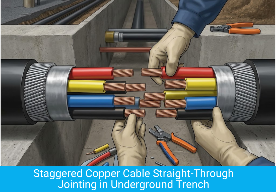
- Apply an outer protective casing, commonly a resin filled mould or a heat shrink outer sleeve, to seal the joint against moisture ingress.
- Test insulation resistance and conductor continuity across the completed joint before backfilling or closing the trench.
Common Termination and Jointing Faults to Avoid
- Loose armour gland connections that leave the armour unearthed, creating a safety hazard during a fault.
- Under crimped or over crimped lugs, both of which increase joint resistance and cause localised heating over time.
- Skipping the insulation resistance test before energising the circuit, which can allow a damaged termination to go into service undetected.
- Using a lug or gland size that does not match the conductor or cable diameter, resulting in a mechanically weak connection.
- Insufficient stripping length, which places mechanical stress on the copper conductor at the point where insulation ends.
Point of Interest
Technical literature on LT cable failures consistently identifies poor termination and jointing practice, rather than cable manufacturing defects, as the leading cause of in service faults on 1.1kV power and control cable networks.
Our Other Product
Building WiresIndoor Versus Outdoor Termination Considerations
Condition | Indoor Termination | Outdoor Termination |
Environmental protection | Heat shrink kit generally sufficient | UV resistant heat shrink or resin filled kit recommended |
Moisture exposure | Low, standard sealing adequate | Higher, gland sealing and boot required |
Temperature variation | Relatively stable | Wider swings, kit rated for outdoor range preferred |
Inspection frequency | Standard preventive maintenance cycle | Shorter cycle due to weather exposure |
Testing and Inspection After Termination
Every completed termination and joint on a 1.1kV copper cable should be tested before the circuit is energised. Insulation resistance testing with a megger confirms there is no breakdown path between conductors or to earth. Continuity testing confirms the conductor and armour paths are complete. Where feasible, a thermal scan of terminations after a period of loaded operation helps identify any high resistance joint before it develops into a fault, since a poor connection typically shows a localised temperature rise well before it fails completely.
Our Other Product
Special CablesSafety Precautions During Copper Cable Termination Work
Record Type | Information Captured |
Termination schedule | Cable tag, from and to location, conductor size, termination kit used |
Crimping record | Lug size, die used, crimping tool calibration reference |
Insulation resistance test log | Phase to phase and phase to earth readings, test voltage, date |
Torque record | Terminal torque values applied against equipment manufacturer specification |
Joint location record | Chainage or coordinates of any straight through joints on buried runs |
Termination and jointing work is carried out on cables that will eventually carry live current, and safe practice at the time of installation reduces risk both during the work itself and for the entire service life of the connection that follows. Site teams should treat every termination as a permanent part of the installation rather than a temporary fix, since a shortcut taken during termination often surfaces months later as an unexplained trip or a hot spot found during thermal inspection.
- Confirm the cable and circuit are isolated and locked out before starting termination work.
- Verify the correct cable has been identified using cable tags or as built drawings before cutting into the sheath.
- Use insulated tools and appropriate personal protective equipment when working near live sections of a switchboard or panel.
- Keep termination kits, lugs and crimping dies matched to the exact conductor size specified by the kit manufacturer.
- Store heat shrink and resin kits according to manufacturer shelf life guidance, since aged material can affect the quality of the seal.
Testimonials
“Good quality 1.1kV copper cables from Capital Cables. The team was helpful with termination and jointing guidance, and the delivery was on time. Overall, a reliable supplier.”
– Rajesh Patel
Documentation Required for Cable Termination and Jointing Records
Good documentation turns a one time termination activity into a traceable record that supports future maintenance, fault finding and warranty claims. Site teams commissioning 1.1kV copper cable terminations should maintain records that allow any future engineer to understand exactly what was installed, tested and signed off at each termination point.
Why Correct Termination Protects Cable Investment
A correctly terminated and jointed 1.1kV copper cable performs to the same standard as the cable itself, often for several decades of service. Capital Cables (India) Pvt. Ltd. supplies 1.1kV copper armoured and unarmoured cable manufactured to consistent quality standards, and recommends that termination and jointing work always be carried out by trained personnel using calibrated tools, so that the reliability built into the cable at the factory is preserved through to the final connection at site.
Maintenance Inspection Schedule for Terminated Copper Cable
A periodic inspection schedule helps catch termination degradation before it results in an unplanned outage. Maintenance teams typically combine visual inspection, thermal scanning and periodic insulation resistance testing on a defined cycle that reflects the criticality of the circuit and the environment in which it operates.
Inspection Activity | Recommended Frequency for Critical Circuits |
Visual inspection of gland and termination | Every six months |
Thermal scan of loaded terminations | Annually, or after significant load changes |
Insulation resistance test | Annually as part of preventive maintenance |
Torque check on accessible terminal connections | Every two years or per equipment manufacturer guidance |
Following a defined inspection schedule for terminations, rather than relying only on breakdown response, extends the practical service life of a 1.1kV copper cable installation and reduces the likelihood of unplanned production stoppages caused by a single weak connection point.
Table of Contents