

Table of Contents
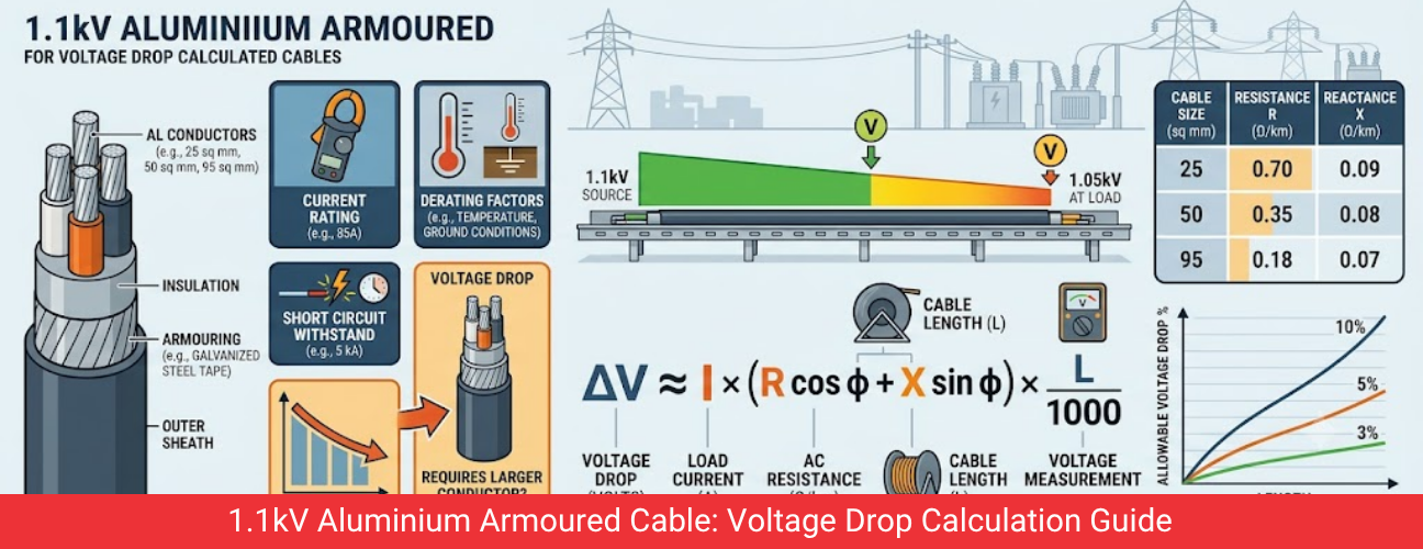
Voltage drop calculation is one of the four checks, alongside current rating, derating and short circuit withstand, that decide the final conductor size of an 1.1kV aluminium armoured cable. On long cable runs, voltage drop frequently becomes the governing factor, forcing a larger conductor than current rating alone would suggest. This guide sets out the formula, reference values and practical limits used to calculate voltage drop for LT aluminium power cable on Indian projects.
Why Voltage Drop Matters for Aluminium Armoured Cable Design
Every metre of cable has resistance and reactance, and current flowing through that impedance causes a small loss of voltage between the source and the connected equipment. If the voltage reaching a motor, panel or lighting fixture falls too far below the rated supply voltage, equipment can underperform, motors can draw higher current to deliver the same output, and sensitive electronic loads can behave unpredictably. Because aluminium has lower conductivity than copper, an aluminium armoured cable of a given cross section experiences a larger voltage drop than a copper cable of the same size carrying the same current, which makes this calculation especially important when aluminium is selected for cost or weight reasons on long runs.
Voltage Drop Formula for Three Phase Aluminium Cable Circuits
The standard approximate formula for three phase voltage drop is Voltage Drop equals root three multiplied by current in Amps multiplied by cable length in kilometres multiplied by cable impedance in ohms per kilometre. This value is then expressed as a percentage of the system voltage, 1.1kV or 415 volts line to line in most LT distribution circuits, and compared against the project specification limit.
- Determine the design current of the circuit from the load schedule or equipment nameplate rating.
- Obtain the resistance and reactance per kilometre for the selected conductor size from the manufacturer cable datasheet.
- Calculate the total cable length from source panel to the connected load along the actual routed path, not the straight line distance.
- Apply the three phase voltage drop formula to calculate the drop in volts for the selected conductor size.
- Convert the result to a percentage of system voltage and compare it against the permitted limit stated in the project specification.
- If the percentage exceeds the limit, select the next larger standard conductor size and repeat the calculation until the drop falls within the permitted range.
Voltage Drop Formula for Single Phase Aluminium Cable Circuits
For single phase circuits, the formula changes slightly, becoming Voltage Drop equals two multiplied by current multiplied by cable length multiplied by impedance per kilometre. The factor of two accounts for the current flowing out through the phase conductor and returning through the neutral conductor, both of which contribute to the total voltage lost along the circuit.
Reference Resistance Values for Aluminium Conductor Sizes
Conductor Size (sq mm) | Approximate Resistance (ohm per km at 90 deg C) |
16 | 2.35 |
25 | 1.50 |
35 | 1.07 |
50 | 0.80 |
70 | 0.55 |
95 | 0.40 |
120 | 0.32 |
150 | 0.26 |
185 | 0.21 |
240 | 0.16 |
300 | 0.13 |
These values are indicative reference figures for stranded aluminium conductors and vary slightly between manufacturers and standards. Final voltage drop calculations should always use the resistance value stated in the specific cable datasheet for the product being ordered.
Read Our Article
Havells Dealer in DelhiPermitted Voltage Drop Limits Used in Indian Projects
Circuit Type | Typical Permitted Voltage Drop |
Power circuits, general | 3 percent of system voltage |
Lighting circuits | 5 percent of system voltage |
Motor circuits with frequent starting | 3 percent, with additional check on starting voltage dip |
Data centre and sensitive electronic loads | 2 percent, project specification dependent |
These limits are commonly used defaults, and the actual permitted value for any project should be confirmed against the electrical specification, equipment manufacturer requirements and applicable code, since certain sensitive loads call for tighter limits than the general defaults shown above.
Point of Interest
A study of LT distribution networks published in electrical engineering literature has noted that voltage drop, rather than thermal current rating, governs conductor selection on a significant share of long feeder circuits in industrial and infrastructure projects, particularly where aluminium conductors are used for cost efficiency.
Practical Example of Aluminium Cable Voltage Drop Calculation
Consider a three phase motor circuit drawing 100 Amps over a cable route length of 120 metres, using a 50 sq mm four core aluminium armoured cable with a resistance of approximately 0.80 ohm per kilometre. Applying the formula, Voltage Drop equals 1.732 multiplied by 100 multiplied by 0.12 multiplied by 0.80, giving a result of approximately 16.6 volts. Expressed as a percentage of 415 volts, this equals roughly 4 percent, which exceeds the typical 3 percent limit for power circuits, meaning the design should move to the next larger conductor size, commonly 70 sq mm, and repeat the calculation to confirm compliance.
Our Other Cables
1.1Kv Aluminium 3.5 Core (Armoured) CableFactors That Increase Voltage Drop Beyond the Basic Calculation
- Higher operating temperature increases conductor resistance, so calculations at full load current should use resistance values at the expected operating temperature, not at 20 degrees Celsius.
- Power factor below unity increases the reactive component of voltage drop, which matters more on longer cable runs with significant reactance.
- Voltage drop across multiple cable sections in series, for example transformer to main panel and main panel to sub panel, must be added together and checked against the cumulative limit for the full circuit path.
- Harmonics from variable frequency drives and other non linear loads can increase effective current and should be considered on circuits feeding such equipment.
Balancing Voltage Drop Against Cable Cost for Aluminium Feeders
Increasing conductor size purely to satisfy voltage drop adds material cost, so consultants often evaluate whether relocating the distribution panel closer to the load, splitting a long feeder into two shorter sections, or switching a specific run from aluminium to copper is more cost effective than stepping up the aluminium conductor size by two or three standard sizes. On very long outdoor runs, however, a larger aluminium conductor typically remains the most economical solution once installation weight and material cost are compared against the equivalent copper alternative.

Getting Accurate Aluminium Armoured Cable Data for Voltage Drop Studies
Accurate voltage drop calculation depends on using the correct resistance and reactance values for the specific cable construction being installed, since these figures vary between manufacturers and between PVC and XLPE insulated designs. Capital Cables (India) Pvt. Ltd. supplies 1.1kV aluminium armoured cable from leading Indian brands and provides datasheets with the technical values needed for consultants to complete voltage drop studies accurately during project design.
Voltage Drop Across Multi Segment Cable Routes
Many real world circuits are not a single continuous cable run but a series of segments, for example a feeder from a transformer to a main panel, followed by a separate cable from the main panel to a sub panel, and a further cable from the sub panel to the final load. Each segment contributes its own voltage drop, and the cumulative drop across all segments in the path must be checked against the overall permitted limit for the complete circuit, not just against the limit for each individual segment considered in isolation.
- Calculate voltage drop separately for each cable segment in the path from source to load.
- Add the percentage drop from each segment together to find the total drop experienced by the final load.
- Compare the cumulative total against the permitted limit for the complete circuit, which is usually the same limit applied to a single continuous run.
- Where cumulative drop exceeds the limit, evaluate which individual segment offers the most practical opportunity to increase conductor size.
Voltage Drop and Motor Starting Performance
Motor circuits deserve particular attention during voltage drop calculation because starting current can be five to seven times the running current for a brief period during direct on line starting. A cable sized adequately for running current voltage drop may still cause an excessive voltage dip at the motor terminals during starting, which can prevent the motor from developing sufficient starting torque or trigger a nuisance trip on undervoltage protection. Consultants working on motor feeders should check voltage drop under both running and starting conditions before finalising the aluminium armoured cable size.
Using Software Tools Alongside Manual Voltage Drop Calculation
While the manual formula approach described in this guide remains useful for quick checks and for understanding the underlying principles, many consulting firms use electrical design software to run voltage drop calculations across an entire distribution network simultaneously, accounting for cumulative drop across multiple segments, diversity factors and varying load conditions. These tools rely on the same underlying resistance and reactance data discussed above, so understanding the manual method remains valuable even when software is used for the bulk of project calculations, particularly for verifying software output on critical circuits.
Sourcing Accurate Cable Data for Aluminium Armoured Feeders
Consultants and contractors working on voltage drop sensitive projects benefit from working with a supplier who can provide reliable technical datasheets promptly rather than generic published values. Capital Cables (India) Pvt. Ltd. supplies 1.1kV aluminium armoured cable from established Indian brands and shares product specific resistance and reactance data on request, supporting accurate voltage drop studies at both the design stage and during any later verification of an installed circuit.
Table of Contents