

Table of Contents
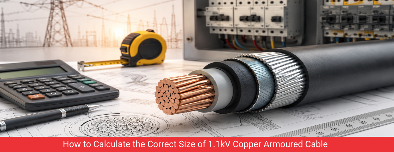
Selecting the correct conductor size for an 1.1kV copper armoured cable is one of the most important calculations an electrical consultant or project engineer performs during design. An undersized cable overheats, trips protective devices and shortens equipment life. An oversized cable increases project cost without adding real value. Capital Cables (India) Pvt. Ltd. supplies 1.1kV copper armoured cable in a wide range of cross sections as an authorised dealer and distributor, and this guide sets out the exact calculation method used by design engineers across India to arrive at the right size for a given load.
Why Copper Armoured Cable Sizing Matters for LT Power Systems
A 1.1kV copper armoured cable carries current from a distribution board, transformer or panel to the connected load. The cross section of the copper conductor decides how much current the cable can carry continuously without exceeding its rated temperature. Copper has higher conductivity than aluminium, so for the same current rating a copper conductor can be smaller in cross section, which is a key reason why copper control cables 1.1kV and copper power cables are preferred in panel wiring, control rooms, hospitals, data centres and instrumentation circuits where space and reliability matter more than raw material cost.
Correct sizing directly affects three outcomes on any project. First, safety, because an undersized cable can overheat the insulation and create a fire risk. Second, energy efficiency, because a cable that is too small increases resistive losses along its length. Third, capital cost, because every additional square millimetre of copper adds to the project budget, so consultants must size cables precisely rather than by rule of thumb.
Key Parameters Used in 1.1kV Copper Cable Size Calculation
Before applying any formula, an engineer needs to gather a set of site and load parameters. These parameters decide the base current rating of the copper armoured cable and the correction factors that are applied to that base rating.
Parameter | Why It Matters | Typical Source |
Load current (Amps) | Decides the minimum conductor cross section required | Equipment nameplate or load schedule |
System voltage | Confirms the cable voltage grade needed, 1.1kV in this case | Single line diagram |
Ambient temperature | High ambient temperature reduces the safe current rating | Site condition or plant location |
Grouping of cables | Cables laid together in trays or trenches derate each other | Cable tray or trench layout |
Installation method | Cables in air, duct, ground or trefoil each have a different rating | Route drawing |
Permissible voltage drop | Long cable runs may require a larger size purely to limit voltage drop | Project specification, usually 3 percent |
Short circuit fault level | Cable must survive fault current for the clearing time of the protective device | Fault study or protection report |
Step by Step Method to Calculate Copper Armoured Cable Size
The following method for 1.1kV copper armoured cable sizing is used by project engineers and is aligned with the approach set out in IS 7098 Part 1 and the CBIP Manual on Power Cables.
- Determine the full load current of the equipment or circuit in Amps, using the formula Current equals kVA divided by root three times voltage for three phase loads, or Current equals kW divided by voltage times power factor for single phase loads.
- Apply a safety margin, typically 1.25 times the full load current for motor circuits, to account for starting current and future growth.
- Select a trial cross section of copper conductor from the manufacturer current rating table for the chosen installation method, for example cable laid in air or buried in ground.
- Apply derating factors for ambient temperature above 30 degrees Celsius, for grouping of multiple cables and for ground thermal resistivity if the cable is buried.
- Compare the derated current rating with the required load current. If the derated rating is lower than the load current, move to the next larger standard size and repeat the check.
- Calculate the voltage drop for the selected size using the cable run length and confirm it stays within the permitted limit, usually 3 percent for power circuits and 5 percent for lighting circuits.
- Verify short circuit withstand capacity of the selected copper conductor against the fault current and clearing time of the upstream breaker or fuse.
- Finalise the cable size only after all four checks, current rating, derating, voltage drop and short circuit withstand, are satisfied together.
Our Other Product
PVC Insulated Winding Wire & 3 Core Flat CablesStandard Current Carrying Capacity Table for Copper Armoured Cable
The table below gives indicative current ratings for XLPE insulated, PVC sheathed, armoured copper cables at 1.1kV, for reference during preliminary sizing. Final selection should always be checked against the manufacturer datasheet and the applicable Indian Standard.
Conductor Size (sq mm) | Current Rating in Air (A) | Current Rating in Ground (A) |
4 | 36 | 42 |
10 | 60 | 68 |
16 | 78 | 88 |
25 | 102 | 112 |
35 | 125 | 135 |
50 | 150 | 160 |
70 | 190 | 198 |
95 | 230 | 235 |
120 | 265 | 268 |
150 | 300 | 300 |
185 | 340 | 335 |
240 | 395 | 385 |
300 | 450 | 430 |
Values vary by manufacturer, number of cores and insulation type, and Capital Cables provides project specific current rating tables for every conductor size it manufactures, from 1.5 sq mm control cores to 400 sq mm power cores.
Testimonials
“Capital Cables provides excellent technical guidance on 1.1kV copper power and control cables. Their explanation of voltage drop calculations is clear, practical, and helpful for making the right cable selection.”
– Rajesh Patel
Voltage Drop Formula for 1.1kV Copper Power and Control Cable
Voltage drop calculation confirms that the equipment at the far end of a long cable run still receives adequate voltage. The approximate three phase formula used by consultants is Voltage Drop equals root three multiplied by current multiplied by cable length multiplied by resistance per kilometre, divided by 1000, expressed in volts. Engineers then convert this to a percentage of system voltage and compare it against the specification limit.
- Short runs under 50 metres rarely govern the sizing decision, and current rating usually decides the conductor size.
- Long runs over 150 metres, common in cement plants, steel plants and airports, are frequently governed by voltage drop rather than current rating alone.
- For distribution boards feeding sensitive electronic loads in data centres and hospitals, a tighter voltage drop limit of around 2 percent is often specified.
Point of Interest
Copper has a resistivity of about 1.72 x 10 to the power minus 8 ohm metre at 20 degrees Celsius, roughly 60 percent lower than aluminium, which is why copper armoured cable of a given cross section can carry significantly more current than an equivalent aluminium cable.
Short Circuit Withstand Calculation for Copper Armoured Cable
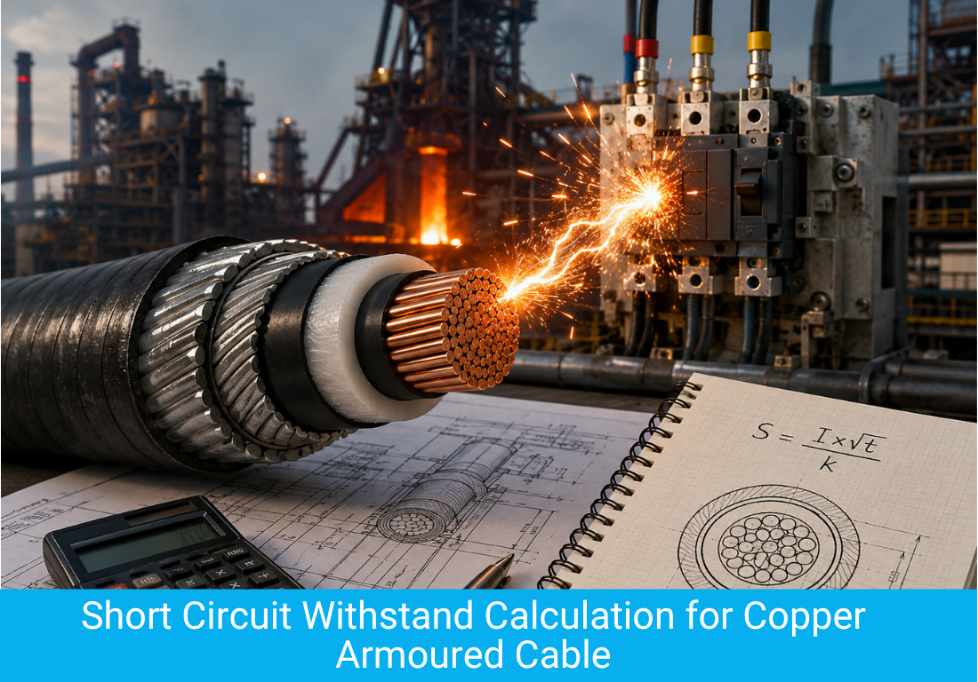
Short circuit rating is checked using the adiabatic equation, where the minimum conductor cross section required equals the fault current multiplied by the square root of the fault clearing time, divided by a constant k that depends on conductor material and insulation type. For copper conductors with XLPE insulation, the k value is commonly taken as 143. This check is critical in industrial plants such as steel plants and refineries where fault levels are high and protection clearing times can extend to a few hundred milliseconds.
Common Errors Engineers Make While Selecting Copper Cable Size
- Sizing purely on current rating without checking voltage drop for long cable runs.
- Ignoring grouping derating when several copper armoured cables run together in a single tray.
- Using aluminium cable current tables by mistake for a copper armoured cable order.
- Overlooking future load growth, which forces cable replacement later at a much higher cost than sizing correctly the first time.
- Not verifying the short circuit withstand capability against the actual fault level at site, especially near large transformers.
Ambient Temperature and Grouping Derating Factors for Copper Cable
Derating factors reduce the base current rating of a copper armoured cable to account for conditions that are hotter than the standard reference temperature used in manufacturer tables, or for the heating effect of several cables running close together. Consultants apply these factors before comparing the cable rating with the required load current, and skipping this step is one of the most frequent reasons an installed cable runs hotter than expected.
Ambient Temperature (Celsius) | Derating Factor for Air Laid Cable |
30 | 1.00 |
35 | 0.94 |
40 | 0.87 |
45 | 0.79 |
50 | 0.71 |
Number of Cables Grouped Together | Derating Factor |
2 | 0.85 |
3 | 0.79 |
4 | 0.75 |
6 | 0.70 |
9 or more | 0.62 |
These derating values are indicative and should be read against the manufacturer datasheet for the specific copper armoured cable being used, since insulation type, sheath material and installation geometry all influence the exact correction factor applied during final sizing.
Our Other Product
Extension/Compensating Leads/cablesCable Sizing Differences for Motor Feeders and Lighting Circuits
Motor feeders and lighting circuits place different demands on a 1.1kV copper armoured cable, and a single sizing rule rarely fits both. Motor feeders draw a starting current several times the running current, so the cable and its protective device must be coordinated to handle that transient without nuisance tripping, while the steady state current rating still governs the final conductor size for continuous operation. Lighting circuits, by contrast, usually operate at a stable current, so voltage drop within the tighter 5 percent limit typically specified for lighting becomes the deciding factor on longer runs, even when the current itself is modest.
- Motor feeders should be sized against full load current with a margin for starting current and coordinated with the upstream protective device.
- Lighting circuits on long runs are frequently governed by voltage drop rather than current carrying capacity.
- Panel to panel distribution cables should include margin for future load additions identified in the electrical load schedule.
How Capital Cables Supports Correct Cable Selection
Capital Cables (India) Pvt. Ltd. supplies 1.1kV copper annealed armoured and unarmoured cable across the full range of standard cross sections, along with copper control cables 1.1kV for panel wiring, sourced from leading Indian brands as an authorised dealer and distributor. Every batch carries the brand manufacturer test certification for conductor resistance, insulation resistance and high voltage withstand, and the technical team supports consultants and EPC contractors with sizing calculations, current rating tables and voltage drop worksheets for their specific project conditions.
Design Check | Governing Standard or Reference |
Current rating and derating | IS 7098 Part 1, CBIP Manual on Power Cables |
Voltage drop limit | Project specification, typically 3 percent |
Short circuit withstand | IS 7098, adiabatic equation with copper k value |
Conductor and insulation testing | IS 8130 for conductor, IS 5831 for PVC insulation |
Table of Contents